Miswired MIDI port.

Discussions related to MegaDrum Hardware

Miswired MIDI port.

Postby WizardOfWoo » Tue Nov 27, 2018 5:18 pm

So, speaking purely hypothetically you understand, what if some moron happened to mix up the ground and pin 2 of the midi I/O and fire up their freshly built megadrum? (AT644 based)

Said moron Noticed that while these MIDI ports were connected, the LCD screen lit up dimly with the MD main power switch off (jumper), but headscratchingly, only when the USB power cable was attached.

^This really my head as i could find no continuity whatsoever anywhere between the LCD and switch pins. Or indeed the switch pins and anywhere else on the board.

But then I realised it only happened with the MIDI ports connected.

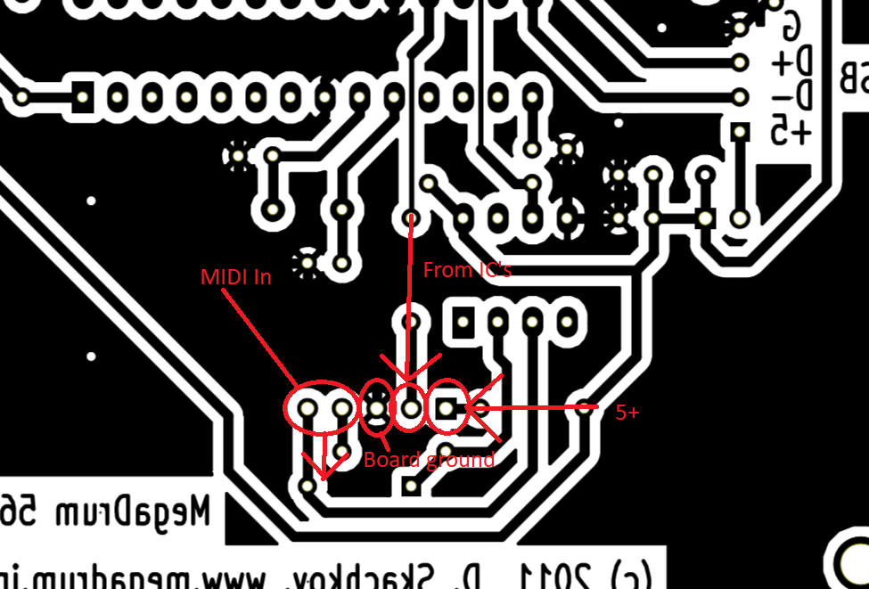
Then I noticed the ground wire mixup.

So from this I infer that power must have been coming from the MIDI-USB cable I had connected and grounding through the USB?

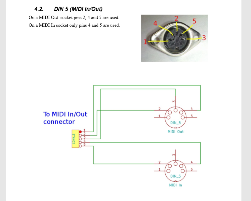
Turns out pins 1 and 2 were also reversed after i fixed the ground problem, so that may have done some damage too (was looking at the schematic like it was the back of the port like a tit).

With this in mind, what damage has said moron likely done to his board?

The midi is definitely not working as expected at the moment.

With the MIDI ports correctly wired, I get no sysex or led activity at all (firmware updater just CRC errors too).

If I connect the MIDI pins backwards on the board (to I and O reversed). I do get sysex and led flashes, but the megadrum drops out of bootloader mode almost the moment I start the update. (which makes some sense to me as there would now be no ground on what it thinks is the midi out)

I have also noticed scrambled characters on the LCD when this happened, but i was moving the board at the time so might just have been dodgy LCD connections.

To be clear, I am indeed the moron in question ;)

I have spares for every component and have been using the PCB from page 2 of this thread https://www.megadrum.info/forums/viewtopic.php?f=3&t=3882&start=10

I'm also still waiting for a PICkit to arrive so I can program the USB firmware, so I can't test anything over that for a couple of days, but will report back when I can.

I already have a couple of ideas but any guidance about which IC pins and components I should pay special attention to would be greatly appreciated.

Regards all.
WizardOfWoo
 
Posts: 20
Joined: Mon Oct 08, 2018 10:45 pm

Re: Miswired MIDI port.

Postby dmitri » Tue Nov 27, 2018 6:44 pm

It really hard to tell if anything was damaged. Just a few notes.
MIDI connection is meant to provide ground and power isolation between connected devices. This is why ground must be connected only on the MIDI Out port and only to provide shielding. The MIDI signal does not use ground at all - it is a current loop. Two signal wires on MIDI Out are connected (over current limiting resistor) to a LED in the optocoupler on the MIDI In port. This optocoupler provides power decoupling between devices.
dmitri
Site Admin
 
Posts: 8657
Joined: Fri Aug 03, 2007 8:05 pm

Re: Miswired MIDI port.

Postby WizardOfWoo » Wed Nov 28, 2018 2:07 pm

Ok thank you.

Perhaps I'm misunderstanding here, but the MIDI out consists of 5V+ in from the board mainline (to MIDI header 1) and presumably loops via pin 15 of the AT644 and pin 25 of the PIC18 back to pin 2 of the MIDI header? (thus forming the loop and letting the AT644 switch said loop to send its signal right?)

And then the MIDI in goes straight to the octocoupler via resistors? (This one is confusing me a little as I can't see how those signal connections make it to the IC's unless its via the LCD? Or does it effectively do it via continuity with the MIDI out?)

So if I understand this correctly; when I mixed up the wires I created the following connections:

1. Connecting the AT644 & PIC pins to MIDI/board ground via 220ohm resistor (what should have been going to Midi out -)
2. Connecting the MD board ground to the MIDI out - and then also the +

I am operating on the assumption that the square pin 1 of the MIDI header is the MIDI out side as per the schematic on the main site.
WizardOfWoo
 
Posts: 20
Joined: Mon Oct 08, 2018 10:45 pm

Re: Miswired MIDI port.

Postby WizardOfWoo » Wed Nov 28, 2018 2:11 pm

Image
WizardOfWoo
 
Posts: 20
Joined: Mon Oct 08, 2018 10:45 pm

Re: Miswired MIDI port.

Postby WizardOfWoo » Wed Nov 28, 2018 2:20 pm

Here's a thought!

I have just noticed in one of your manuals, that the DIN5 pins (on the image of the actual socket) are labelled differently to the schematic.

Have I made a pretty basic error there?

i.e. midi ground is actually bottom right on the DIN not the top middle as it appears on the schematic? etc. etc.

Kind of hoping it is as it would explain a great deal!
WizardOfWoo
 
Posts: 20
Joined: Mon Oct 08, 2018 10:45 pm

Re: Miswired MIDI port.

Postby dmitri » Wed Nov 28, 2018 3:29 pm

1. I'm guessing you connected the ground pin at both ends of the MIDI connection. If those grounds were at different potentials it would have created a current (might be very high current if the difference is high) through the ground wire which could create a potential difference to the power rails thus lighting up LCD and potentially damaging ICs sensitive to voltage levels.

2. The MIDI connector pinout on the board has no relation to the pin numbers on MIDI In and MIDI Out DINs. Both MIDI In and MIDI Out DINs use the same pins 4 and 5 for signal. MIDI Out also uses pin 2 for ground/shielding connection.
dmitri
Site Admin
 
Posts: 8657
Joined: Fri Aug 03, 2007 8:05 pm

Re: Miswired MIDI port.

Postby WizardOfWoo » Wed Nov 28, 2018 5:03 pm

Image

I am referring specifically to that. Where the numbers on the image of the DIN itself appear different to those in the DIN schematic.

I realise the board pins don't translate, but I have wired them such that pin 1 on the board goes to pin 4 on the schematic as shown and so on.

But pin 4 on the photo of the DIN is in a different location to the schematic. Making me think that the schematic doesn't match the actual DIN in terms of location?

If so does that not mean I should be connecting Board 1 to DIN 4 (top left), 2 to DIN 2 (top middle) and ground to DIN 3 (bottom right).

Instead of as shown on the schematic where it goes B1 to D4 (top right), B2 to D2 (top left), and B3 to DIN3 (top middle).

I hope that makes sense?

Otherwise I can't see why you included that photo of the DIN in the manual? (the schematic on the main site dosen't mention this, but it appears to be the same schematic)


EDIT: having checked, the main site schematic (which is the one i actually followed) does appear to follow the same number scheme as the photo. So it's clearly not that.

However I suspect I might have been viewing the schematic backwards if the photo is correct (i.e. the schematic is the DIN as viewed from behind, not the socket side?)
WizardOfWoo
 
Posts: 20
Joined: Mon Oct 08, 2018 10:45 pm

Re: Miswired MIDI port.

Postby WizardOfWoo » Wed Nov 28, 2018 5:20 pm

I never connected more than one pin to ground at a time (Board pin 3)

I understand only MIDI out has a ground wire so there was never any point that, MIDI In and out both had a ground wire. (I assume that's what you mean?)

I just mixed up the pin 2 and 3 wires (& potentially pin 1 & 3 too).

Can;t test till tomorrow, but if i haven't fried the IC inputs, then I assume its just me getting the schematic bassakwards.

Annoying as apart from the ground mix up, I would actually have got it right 1st time. Second guessed myself into thinking I was viewing the schematic backwards. (when it seems like i was in fact viewing the back of the socket)

Sorry for my waffling stupidity but thank you for your help.

Will get there in the end! (I hope)
WizardOfWoo
 
Posts: 20
Joined: Mon Oct 08, 2018 10:45 pm

Re: Miswired MIDI port.

Postby dmitri » Wed Nov 28, 2018 6:55 pm

I'm not sure where got this schematic. In the kits manual it shows:
Screen Shot 2018-11-28 at 18.51.18.png


In both https://www.megadrum.info/schematics.php and viewtopic.php?f=3&t=266 it shows:
Screen Shot 2018-11-28 at 18.53.49.png
You do not have the required permissions to view the files attached to this post.
dmitri
Site Admin
 
Posts: 8657
Joined: Fri Aug 03, 2007 8:05 pm

Re: Miswired MIDI port.

Postby WizardOfWoo » Wed Nov 28, 2018 8:04 pm

Specifically this one https://www.megadrum.info/sites/default/files/MegaDrum%20kit%20-%20instruction%20manual.pdf

But as I say I was using the correct schematic when i actually wired it anyway so should probably have just deleted that part of the post when I worked that out sorry.


But to clarify (as the DINS are the other way around between those schematics)

The schematic on the main MD page (1,5,2,4,3) is showing the back of the MIDI port right?

And then the schematic on the manual you just linked is showing the front? (1,4,2,5,3)

So they are both the same layout, but viewed from opposite directions?

Or do DIN 4&5 not matter which way they are orientated?

Could I also please confirm that the square pin on the PCB picture I posted is indeed MIDI pin 1? (i.e. the MIDI out side)
WizardOfWoo
 
Posts: 20
Joined: Mon Oct 08, 2018 10:45 pm

Next

Return to MegaDrum Hardware

Who is online

Users browsing this forum: Bing [Bot], Majestic-12 [Bot] and 124 guests

cron